
Designing a Race Car From Scratch With Regulations
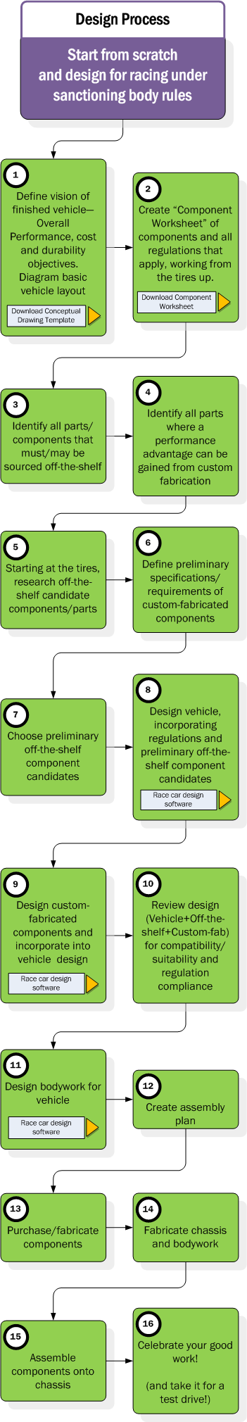
The design process when starting from scratch and designing with a sanctioning body’s regulations is shown below in diagram form. To the right is the description of each step shown in the diagram. There are also buttons included on the diagram which link to resources on our site that you can download to assist you in your design and construction.
Key considerations for this type of design are the restrictions and opportunities created by the regulations and your budget constraints.
This diagram and instructions are also available as a free downloadable, printable PDF version.
PLEASE NOTE: The Conceptual Diagram Template (CDT) and Component Worksheet (CW) documents are provided free to help you create a visual layout and manage components in your race car design. Please download them at your convenience and use them where noted below by the highlighted “CDT” and “CW” text.
- (CDT) The first step is to define ideals and specific objectives for the race vehicle you want to build, within the framework of the regulations you are building to. A combination of vision statement and requirements, you need to layout via words and a conceptual drawing what you wish to see in the final product. This “Vision” for your vehicle will be the reference point when making decisions later. For example:
- DESIGN – The car shall have a maximum weight of 1800 lbs as per minimum weight regulation 2.1.1
- PERFORMANCE – The vehicle shall have a speed of 200 km/h at the end of 1 km from a standing start.
- COST – The total cost of parts should be no more than $4,000.
- (CW) Regulations are applied to each area of the race vehicle when racing under a sanctioning body. To help manage the requirements of the regulations, the regulations can be noted in the “Component worksheet”. Later, when designing, these regulations are able to be quickly referenced next to the component in the worksheet without the need to scan a complex book of rules.
- (CW) Depending on the series, there may be components which are required to be “Off-the-shelf” to save money or give parity to racing. Along with the regulations in #2 above, noting which components are not “Negotiable” is useful. If regulations stipulate a type and not a specific brand/model of a component, then there may be an opportunity to optimize your choice of brand/model.
- (CW) Depending on the nature of the racing, having a custom fabricated part instead of one which is off-the-shelf can be a performance advantage. The performance gained needs to be weighed against the additional costs of custom fabrication.
- (CW) Finding the available brands/models of components and assessing their performance value and cost is next. The goal here is to find “candidates” that would perform as needed and fall within budget.
- (CW) Using the list of components to be custom fabricated, begin laying out specifications/requirements for those components so that when they are being designed, the specifications are available.
- (CW) This can be one of the more time-consuming steps. In #5 above, the available brands/models for each component were researched and listed. Now is the time to choose the most promising brand/model from the list. Each component must be assessed for its compatibility with other components, which can be time consuming. For example, when selecting wheel hubs, they must have a bolt pattern and bolt center that matches the wheels I select. Therefore, both components must be selected with the other in mind. If I change wheels, I may wind up changing the hubs and so on.
- (CW) (CDT) This is the first draft of the vehicle design. Starting with the tires and working your way inboard, design the suspension. Then, using the chassis pickup points, design the chassis. The components selected need to have their key attributes identified. For example, for a wheel hub it is useful to know its face diameter, bolt center diameter, face thickness, inner shaft diameter, and depth. The key is to identify the essential geometries of the component including any attachment points. Aerodynamics should be considered for the vehicle as a whole and for components which rely upon cooling.
- (CW) (CDT) Assuming the vehicle design and all the off-the-shelf components appear to work well in the design, begin designing the custom fabricated components and “Fit” them into the draft design. You may need to go back and refine your design through steps 7 and 8 if there were issues with the draft design.
- (CW) (CDT) At this stage, the vehicle design must be reviewed for completeness, component fit and suitability and regulation compliance. If parts do not work, you may need to return to steps 7 and 8 to revise your component selections and vehicle design. If everything is OK, it would be a good idea to create a full 3D model of all components and the vehicle design. It is at this stage that the full shape of components should be understood so that they don’t interfere with each other.
- (CDT) Once a complete vehicle design is available, bodywork can be designed to fit over it and mount to it.
- (CW) An assembly plan is used to determine the order of assembly. It is just like the instructions you find in the box with most “Some assembly required” products from a store. The plan is created to ensure you don’t spend hours assembling components only to find out you left out a key step and need to start over. It is also useful in long term maintenance documentation.
- (CW) Assuming all is well with design and the assembly plan for it, the build portion of the project begins. Purchase the off-the-shelf components and fabricate the custom designed components
- Fabricate the chassis and bodywork, preferably after the components arrive. Fit and finish can be adjusted when the parts are in your hands.
- Using the assembly plan, assemble components onto the chassis and perform a full fastener inspection to confirm everything is bolted/fastened on as it should be.
- Don’t forget to photo document your vehicle as you are building it and when it is completed. Invite your friends and family to celebrate.
60 9