
Designing a Race Car, Sports Car or Off-road Vehicle From a Base/Donor Vehicle With Your Own Vision
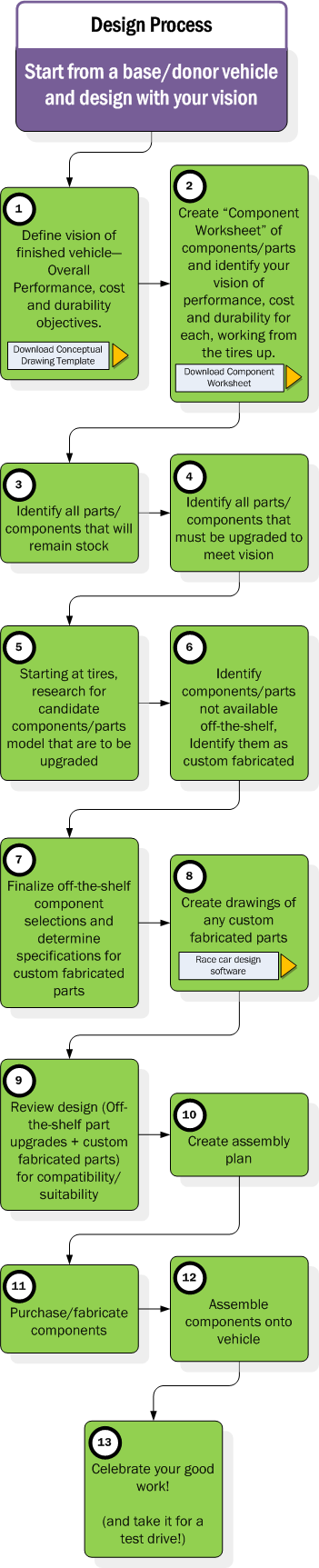
The design process when starting from a donor vehicle and your own vision is shown below in diagram form. To the right is the description of each step shown in the diagram. There are also buttons included on the diagram which link to resources on our site that you can download to assist you in your design and construction.
Key considerations for this type of design are to define your vision for the vehicle thoroughly with consideration for your desired budget, complexity and time commitment.
This diagram and instructions are also available as a free downloadable, printable PDF version.
PLEASE NOTE: The Conceptual Diagram Template (CDT) and Component Worksheet (CW) documents are provided free to help you create a visual layout and manage components in your vehicle design. Please download them at your convenience and use them where noted below by the highlighted “CDT” and “CW” text.
- (CDT) The first step is to define ideals and specific objectives for the vehicle you want to build. A combination of vision statement and requirements, you need to layout via words and a conceptual drawing what you wish to see in the final product. This “Vision” for your vehicle will be the reference point when making decisions later. For example:
- DESIGN – The car shall have a maximum weight of 1800 lbs
- PERFORMANCE – The vehicle shall have a speed of 200 km/h at the end of 1 km from a standing start.
- COST – The total cost of parts should be no more than $4,000.
- (CW) Based on your vision defined in #1, you can determine the qualities you need to focus on in the components. To help manage these qualities, note them in the “Component worksheet” next to each component. For example, if very durable high powered braking is a requirement, then that should be noted next to the brake disc and caliper lines of the component worksheet. Later, when designing, these qualities are able to be quickly referenced next to the component in the worksheet.
- (CW) Depending on your vision, there may be components which can remain as stock. These should be noted in the worksheet
- (CW) Identify the parts that need to be upgraded to meet your vision for the vehicle. At this stage, whether they are off-the-shelf or custom fabricated is not important. The immediate goal is to identify what component changes support the vision.
- (CW) Find available off-the-shelf brands/models of components you intend to upgrade and assess their performance value and cost. The goal here is to find “candidates” that would perform as needed and fall within budget.
- (CW) Identify components which do not meet your vision with off-the-shelf brands/models. The performance gained needs to be weighed against the additional costs of custom fabrication.
- (a) (CW) This can be one of the more time-consuming steps. In #5 above, the available brands/models for each component were researched and listed. Now is the time to choose the most promising brand/model from the list. Each component must be assessed for its compatibility with other components, which can be time consuming. For example, when selecting wheel hubs, they must have a bolt pattern and bolt center that matches the wheels I select. Therefore, both components must be selected with the other in mind. If I change wheels, I may wind up changing the hubs and so on.
(b) (CW) Using the list of components to be custom fabricated, begin laying out specifications/requirements for those components so that when they are being designed, the specifications are available. - (CW) Create your drawings for the custom fabricated components. These must fit with the off-the-shelf selections from #7a above and with the donor vehicle. If the donor vehicle chassis requires modifications, you will need to create a vehicle design to model these changes and incorporate the off-the-shelf and custom fabricated components.
- (CW) (CDT) At this stage, the overall vehicle design must be reviewed for completeness, component fit, suitability and safety. If parts do not work, you may need to return to steps 7 and 8 to revise your component selections and vehicle design. If everything is OK, it would be a good idea to create a full 3D model of all components and the vehicle design or to use the classic pencil and paper to draft various views of the component assemblies and the overall vehicle design. It is at this stage that the full shape of components should be understood so that they don’t interfere with each other.
- (CW) An assembly plan is used to determine the order of assembly. It is just like the instructions you find in the box with most “Some assembly required” products from a store. The plan is created to ensure you don’t spend hours assembling components only to find out you left out a key step and need to start over. It is also useful in long term maintenance documentation.
- (CW) Assuming all is well with design and the assembly plan for it, the build portion of the project begins. Purchase the off-the-shelf components and fabricate the custom designed components
- Using the assembly plan, assemble components onto the chassis and perform a full fastener inspection to confirm everything is bolted/fastened on as it should be.
- Don’t forget to photo document your vehicle as you are building it and when it is completed. Invite your friends and family to celebrate.
33 1